Real-Time Model Predictive Control
for Structural Engineering

INTRODUCTION
Structural control devices have been implemented in a wide variety of structures, including bridges, tall buildings, and offshore structures. The performance of such systems under environmental loads has been improved greatly as a result of theoretical and experimental research and related development efforts (Soong, 1990; Suhardjo et al., 1992; Yang et al., 1994; Lopez-Almansa et al., 1994; Suhardjo and Kareem, 1997; Structural Control, 1994, 1998). A comprehensive review of theoretical developments in control design can be found in Housner et al. (1997). Details concerning their applications to real structures were reviewed by Kareem et al. (1999). The first application of active control system to a full-scale building was the Kyobashi Seiwa Building located in Tokyo in 1989 (Figure 1). More than 20 buildings in Japan have since then been equipped with active control systems. One example of a recent application of a V-Shaped hybrid mass damper concerns the Shinjuka Park Tower (Fig. 2)in Japan. Two recent application of passive tuned mass dampers include Washington Reagan airport and Park Hyatt Hotel in Chicago.
There are different control strategies
that have been examined in the literature. The most commonly used scheme in
controller design is the Linear Quadratic Regulator (LQR). Other schemes of
interest include the ![]() ,
, ![]() , sliding mode control and predictive control for application
to civil engineering structures (Housner et
al., 1997).
, sliding mode control and predictive control for application
to civil engineering structures (Housner et
al., 1997).
At the NatHaz Modeling Laboratory at the University of Notre Dame, researchers are studying the design and development of the Model Predictive Control (MPC) scheme which has been effectively used in chemical, automotive and aerospace industries (Morari et al., 1994). It has been effectively shown to be feasible for structural control applications by Mei et al. (1998). The MPC scheme is based on an explicit use of a prediction model of the system response to obtain the control action by minimizing an objective function. Optimization objectives include minimization of the difference between the predicted and reference response and minimization of the control effort subjected to constraints. MPC offers a general framework of posing the control problem in the time domain and can be used to integrate issues of the optimal control, stochastic control, control of processes with time delays and multivariable control.
|
Figure 1(a) Kyobashi Seiwa Building
using AMD |
Figure 1(b) The Active mass Damper |
|
Figure 2(a) Shinjuku Tower using HMD |
Figure 2(b) The V-shaped HMD |
MPC-BASED CONTROL SCHEMES
The
general MPC scheme has a reference trajectory, ![]() , specified. This trajectory represents the desired target
trajectory for the system response. An appropriate prediction model is used to
predict the future system responses,
, specified. This trajectory represents the desired target
trajectory for the system response. An appropriate prediction model is used to
predict the future system responses, ![]() . The prediction is made over a preestablished extended time
horizon, using the current time as the prediction origin. For a discrete time
model, this means predicting
. The prediction is made over a preestablished extended time
horizon, using the current time as the prediction origin. For a discrete time
model, this means predicting ![]() ,
, ![]() , … ,
, … , ![]() for i sample times in the future. This
prediction is based on both actual past control inputs
for i sample times in the future. This
prediction is based on both actual past control inputs ![]() ,
, ![]() , … ,
, … , ![]() and on the sequence of future control efforts determined
using the prediction model that are needed to satisfy a prescribed optimization
objective. This includes minimization of the difference between the predicted
and the target response and minimization of the control effort needed to reach
this objective subjected to certain constraints, such as limits on the
magnitude of the control force. The control signals that were determined using
the prediction model are then applied to the structure, and the actual system
output,
and on the sequence of future control efforts determined
using the prediction model that are needed to satisfy a prescribed optimization
objective. This includes minimization of the difference between the predicted
and the target response and minimization of the control effort needed to reach
this objective subjected to certain constraints, such as limits on the
magnitude of the control force. The control signals that were determined using
the prediction model are then applied to the structure, and the actual system
output, ![]() , is evaluated. Finally,
the actual measurement,
, is evaluated. Finally,
the actual measurement, ![]() , is compared to the model prediction
, is compared to the model prediction ![]() and the prediction
error is utilized to update future predictions.
and the prediction
error is utilized to update future predictions.
|
Figure 3 Basic Model Predictive Control scheme |
1. Unconstrained MPC Scheme
For the non-constrained problem, the following objective function is employed
![]()
By minimizing J, the optimal predictive control force is given by
![]()
The performance of MPC scheme is
compared to the ![]() control strategies. The results demonstrate that the
effectiveness of the
control strategies. The results demonstrate that the
effectiveness of the ![]() and MPC schemes is
equivalent. Using the same control force MPC reduces the displacement response
to the level reached by
and MPC schemes is
equivalent. Using the same control force MPC reduces the displacement response
to the level reached by ![]() control scheme (Mei,
et al, 1998, 2000).
control scheme (Mei,
et al, 1998, 2000).
2. Real-time FF-FB MPC-AR scheme
Most of the control strategies reposrted in the literature have beeb based only on the feedforward control. However, some studies also utilized a feedforward compensator which works in conjunction with a feedback loop (Suhardjo et al, 1990 and 1992). In the feedforward-feedback (FF-FB) scheme, the equations of structural motion are augmented with an appropriate state space excitation model of the ground motion. The feedfowarded information from ground motion and feedback help controller together to achieve better performance than the feedback only control design.
The real-time FF-FB MPC scheme can be
formulated by introducing the ground acceleration time history fitted to a
time-varying auto-regressive (AR) model to reflect the non-stationary features
of the ground motion. At each time instant ![]() , a p-dimensional AR model is formulated using the
Yule-Walker equation. The error between the measured and the modeled excitation
is then obtained at each step. The AR model is cast in the state-space form and
is subsequently embedded in the overall system state-space equations.
, a p-dimensional AR model is formulated using the
Yule-Walker equation. The error between the measured and the modeled excitation
is then obtained at each step. The AR model is cast in the state-space form and
is subsequently embedded in the overall system state-space equations.
The building and the earthquake models are then combined to establish an augmented overall system model. For this case the control force is
![]()
3. Constrained MPC scheme
One important practical concern in control design is the influence of physical constraints that are imposed on structures and control actuators. For example, active mass dampers are constrained by their stroke and their capacity to generate force. The MPC based scheme explicitly considers these constraints in the objective function and provide an optimum solution with constraints. For the contrained problem, the objective function is given by
![]()
![]()
subjected to the linear inequality constraints:
This can be solved as a standard quadratic programming problem. The optimal solution is obtained within the restricted range in the given state space. Therefore, although the optimal points may not be the optimal solution in the entire space which is the unconstraint case, it is optimal within the constrained space. The quadratic problem is solved using an active set strategy. It searches an initial feasible solution by first solving a linear programming problem. Then an iterative sequence of feasible points is generated that converges to the solution. The optimal predictive control force is obtained by an optimal value in the constraint set which minimizes the objective function.
|
Figure 4 MPC
based schemes for earthquakes |
REAL-TIME MPC-AR
SCHEME
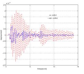
The FF based on AR modeling provides a practical way to apply the FF-FB control scheme more effectively. The 1940 El Centro earhtquake record was used in this analysis to excite the example building. Both the displacement and acceleration responses are significantly reduced in the presence of the controller. Table 1. lists comparisons of the response using no control, MPC alone, and MPC-AR (Figs. 5 and 6). The results show that when the MPC-AR model was used, the control performance was better than the scheme using MPC alone and furthermore, the control force was smaller. Clearly, the FF-FB control is more effective than the FB only control scheme.
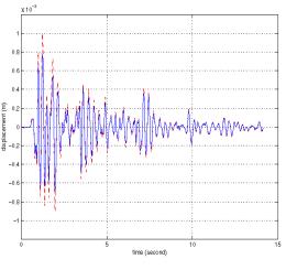
The Kobe and Hachinohe earthquake acceleration time histories were used as inputs to assess the effectiveness and robustness of the MPC-AR control scheme. As shown in Table 2 and Figs. 7 and 8, the structural response was reduced significantly when the MPC-AR scheme was employed. These results suggest that the real-time MPC-AR based model was very effective in controlling a wide range of earthquakes with their own distinct features (Mei, et al, 2000a).
|
Figure 5 Displacement response without control (---) and with control using MPC-AR scheme (___) |
Figure 6 Controlled displacement response using MPC only (---) and MPC-AR scheme(___) |
|
Figure 7 Displacement response without control (---) and with control using MPC-AR scheme (___) under Kobe earthquake |
Figure 8 Displacement response without control (---) and with control using MPC-AR scheme (___) under Hachinohe earthquake |
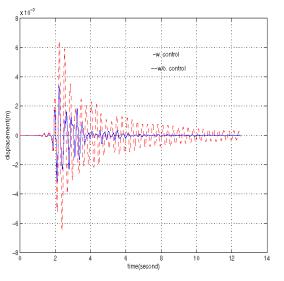
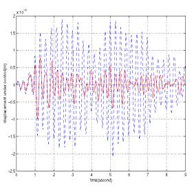
Table 1 Comparison between the MPC-AR and MPC under El Centro Earthquake
|
|
(cm) |
(cm/s2) |
(kN) |
(cm) |
(cm/s2) |
(kN) |
|
No Control |
0.075 |
37.8 |
|
0.25 |
135.4 |
|
|
MPC |
0.020 |
14.6 |
0.099 |
0.10 |
101.5 |
0.672 |
|
MPC-AR |
0.016 |
13.4 |
0.083 |
0.078 |
95.1 |
0.622 |
Table 2 Performance of MPC-AR scheme under Kobe and Hachinohe Earthquakes
|
|
|
(cm) |
(cm/s2) |
(kN) |
(cm) |
(cm/s2) |
(kN) |
|
Kobe Earthquake |
No Control |
0.126 |
68.8 |
|
0.67 |
466.9 |
|
|
MPC-AR |
0.0541 |
40.4 |
0.275 |
0.35 |
307.5 |
2.31 |
|
|
Hachinohe Earthquake |
No Control |
0.0913 |
45.8 |
|
0.21 |
106.3 |
|
|
MPC-AR |
0.0277 |
16.7 |
0.073 |
0.10 |
71.19 |
0.282 |
CONSTRAINED MPC
SCHEME
The controlled response using MPC with strict constraints was then studied. The constraint on the control force was set as [-800, 800] N. Furthermore, the increase or decrease in the control force at each time step could not exceed 100N. The example building used earlier is employed for this control design. In Fig. 9 (a) the control force is plotted. As shown, the control force did not go beyond the 800 N limit. In Fig. 9 (b) the change in the control force at each step is shown. The change in force did not exceed 100N at each step as required by the constraints. These figures show that the constraints are handled in the MPC scheme effectively. The optimal control force was quite different from the control force obtained by using saturation. The MPC scheme offers an optimal solution considering the limitation on control force. The maximum control force reached at a time instant will affect the future control force and response. The root mean square and peak values of displacement, acceleration and control force are listed in Tabel 3.
The response properties were slightly different than when no constraints were used. There was a slight increase in both the RMS and peak displacement and acceleration responses. However, when strict constraints were used, the peak value of control force is 33% less than that when no constraints were used, and the increment in the control force is 52.3% smaller than that when no contstraints were used. The root mean square value of the control force was slightlly larger than that when no constraints were used. This increase was caused by the constraints, which make the control force change rather slowly and have more peak-valued control force valuesthan when no constraints were used. Although the control forces were greatly reduced by the constraints acting on them, there is little change in the controlled response due to the optimal design of MPC. This means a more economical actuator can be used based on MPC to achieve the level of control performance obtained under unconstrained conditions (Mei, et al, 2001).
|
Figure 9 (a) and (b)
Control force and increment of control force at each time step |

Table
3. Comparison between the MPC without constraints and with Constraints
|
|
|
|
|
|
|
|
|
|
without control |
0.075 |
37.8 |
|
0.25 |
135.4 |
|
|
|
MPC w/o constraints |
0.016 |
17.1 |
177.5 |
0.081 |
114.9 |
1205.5 |
210.5 |
|
MPC w. constraints |
0.019 |
18.2 |
183.5 |
0.12 |
126.3 |
799.99 |
99.99 |
Semi-active control scheme
Semi-active control devices provide some of the best features of both the passive and active control systems. Many of these can be operated by a battery, which is critical during the seismic events in case the main power systems fails. They can achieve almost the same control effectiveness as the active cotnrol, and yet then do not have the potential to destabilize the structure system under a variety of dynamics loading conditions (Housner et al, 1997). For the Semi-Active Mass Damper (SAMD), a variable orifce damper is involved and the control force is usually generated according to:
![]() ,
,
![]() is the relative velocity of mass damper to the building, and
is the relative velocity of mass damper to the building, and ![]() is the desired control force which is obtained from optimal
control scheme. Assume the maximum control force the mass damper can generate
is 7 lbs. Here a time varying constrained MPC scheme was applied to make the
control force within the damper capability. Therefore, the following limits
were derived:
is the desired control force which is obtained from optimal
control scheme. Assume the maximum control force the mass damper can generate
is 7 lbs. Here a time varying constrained MPC scheme was applied to make the
control force within the damper capability. Therefore, the following limits
were derived:
if ![]() ,
, ![]() ; if
; if![]() ,
, ![]()
These constraints were switched between
the two cases according to the direction of the relative velocity, which was
changing by time. So these were time-varying and need to be updated at each
step of the generated control force. MPC constrained scheme provides an optimal
solution within these time-varying constraints. Figure 6 shows the changing of
the constraints with respect to the relative velocity of mass damper and the
desired control force. The damping force is generated at the second and forth
quadrant only. At the first and third quadrant, the damping force is zero.
Therefore, the constraints are ![]() and 0 in the left plane and 0 and
and 0 in the left plane and 0 and ![]() in the right plane.
in the right plane.
|
Figure 10 Time
varying constraints for SAMD |
ACCELERATION FEEDBACK AND STATE FEEDBACK
As stated earlier, acceleration is a more straightforward and convenient response to measure than the displacement and velocity response, which define the states of the system. The main assumption invoked here involves the use of the Kalman filter in the MPC scheme assuming that the input and output disturbances are random with zero mean values (Ricker, 1990). According to the separation principle, the control and estimation problems could be considered separately. Therefore, the estimator gain can be obtained independent of the feedback gain. The full state vector is reconstructed using an observer to obtain the estimate of the state vector.
Analysis of the SDOF system using MPC with acceleration feedback was compared to the analysis using MPC with state (i.e. displacement and velocity) feedback. In the former case, an observer was used to estimate the states of the system using the measured acceleration output (Mei, et al., 2000b).
experimental Validation
Tests were conducted at the NatHaz Modeling Laboratory to validate the numerical schemes. The test equipment included a small-scale two-story building, a small-scale shaking table, an active mass damper, a data acquisition I/O board, a signal spectrum analyzer, accelerometers and a desktop computer (Fig. 11).
|
Figure 11
Small-scale two-story building with active mass damper on shaking table |
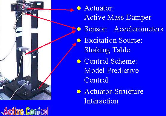
The small-scale shaking table consists of an electric powered servo motor, a flat table mounted on one linear high-accuracy drive shaft and two 64 cm long sliding tracks. A two story test building employed in the experiment was a flexible scale-model. This structure can be configured to have 2 floors. The height of each floor was 490 mm with two steel columns in the dimension of 2x108x490 mm3. The mass of each column was 0.227kg. The first floor mass was 4.8kg. The mass of the second floor including AMD was 5.0 kg, which was a direct drive linear motion cart driven by a high torque DC motor. Accelerometers were attached at each floor. A Multi-I/O board was used for data acquisition and analysis. It was used to obtain the measured response from sensors and to send control signal to the shaking table and AMD.
|
Figure 12
System identification including controller-structure interaction |
The entire system was identified by using curve-fitting and Eigenvalue Realization Algorithm (ERA). The dynamics of AMD and interaction between the AMD and structure are taken into considered in the equations of motion (Fig. 12). The MPC scheme can greatly reduce the acceleration at each floor. There is only a small variance between the experimental and simulation response values (Table 4).
Table 4
Response of the Building using MPC Scheme
|
|
|
|
|
|
|
|
|
No Control |
0.4293 |
0.3784 |
|
1.397 |
1.211 |
|
|
Controlled (experiment) |
0.2409 |
0.2191 |
0.0520 |
0.9308 |
0.9524 |
0.2195 |
|
Controlled (simulation) |
0.2215 |
0.1859 |
0.0472 |
0.9056 |
0.8801 |
0.2090 |
Feedforward-Feedback Control for Wind-Excited Building
Wind loads often govern the design of tall buildings and flexible structures even in strong seismic zones. Strong winds can make occupants feel uncomfortable and even cause the failure of structure and death of people. Therefore, how to reduce the response of structure under wind load is a big issue in structure design and structure control fields.
Researchers in NatHaz have proposed new methods for modeling the wind load. The proper orthorgonal decompasition (POD) of wind field proposed by Kareem and Mei (1999) is used to derive state space representation of wind load with desired spectral matrix. First, spectral matrix of wind load is decomposed into eigenvalue and eigenvectors at each frequency. Therefore the eigenvalue are a diagonal spectral matrix. Autoregressive model is used to obtain the state space representation of wind load whose spectrums match the eigenvalue spectra obtained. Then eigenvectors are utilized to transform the final state space representation of wind load. Independent white noises are generated as the inputs to the wind model. This filtering process outputs the desired wind load. By using this method a feedforward link is established. This feedfoward-feedback combined method based on MPC scheme is used for the response reduction of Nanjing Tower.
Benchmark Problem For Wind Excited Tall Buildings
As mention before, a wide range of control devices and schemes have been proposed and implemented in tall buildings to enhance their habitability and response reduction in strong winds and moderate earthquake. However, it is very difficulty to evaluate these schemes because they have different control devices, different design criteria and different backgrounds. Yang et al (1998) proposed a benchmark problem for wind-excited buildings at the second world conference of structural control which is known as the second generation of wind-excited benchmark problem. Therefore, the performance of different methods and devices could have the same design objectives and have the same basic backgrounds to be compared. After that some alternations have been done. In Yang et al. (1999) a third generation benchmark problem of wind-excited tall buildings has been proposed. In this version of benchmark problem, a significant alternation is that the wind load time histories were obtained from a wind tunnel test in Sydney University for use in the time domain analysis.
A reduced order model for the 76-story concrete building is controlled by using MPC. The MPC provides an alternative simple control method and can handle constrained problems conveniently (Mei and Kareem, 1998a). MPC based schemes were studied in NatHaz. The inequality constraints on the maximum control force and AMD displacement are included in optimal objective. At each time step MPC reduces to an optimal problem subject to inequality constraints. A quadratic programming algorithm is used to obtain the optimal control force. Optimal solution is found in this constrained space. Therefore, the control forces and AMD displacement are kept within the constrained space.
The research projects on the active control schemes based on MPC have demonstrated the efficacy of MPC scheme in controlling structural motions under earthquakes or strong winds and provided the framework for capturing the attractive features of MPC, i.e., computational expediency, real-time applications and constraints. The experimental validation of MPC demonstrated the potential application of the MPC scheme to full-scale structural control problems.
Acknowledgement
The support for this work was provided in part by the National Science Foundation Grants CMS-94-02196 and CMS-95-03779 under the NSF Structure Control Initiative. This support is gratefully acknowledged.
REFERENCES
Housner, G., Bergman, L. A., Caughey, T. K., Chassiakos, A. G., Claus, R. O., Masri, S. F., Skelton, R. E., Soong, T. T., Spencer, B. F., Yao, J. T. P. (1997), “Structural Control: Past, Present, and Future.” ASCE, J. Engrg. Mech., Vol. 123, No. 9, 897-971.
Hrovat, D., Barak, P., and Rabins, M. (1983), “Semi-Active Versus Passive or Active Tuned Mass Dampers for Structural Control”, J. of Engineering Mechanics, ASCE, Vol. 109, No. 3, 691-705.
Kareem, A. (1994), “The Next Generation of Tuned Liquid Dampers”, Proceedings of the First World Conference on Structural Control, Vol. I, Los Angels.
Kareem, A., Kijewski, T. and Tamura Y. (1999), “Mitigation of Motions of Tall Buildings with Specific Examples of Recent Applications”, Wind & Structures Vol. 2, No. 3, 201-251
\Lopez-Almansa, F., Andrade, R., Rodellar, J. and Reinhorn A. M. (1994), “Modal Predictive Control of Structures I and II” ASCE, J. Engrg. Mech., Vol. 120, No. 8, 1743-1760, 1761-1772.
Makris, N., Hill, D., Burton, S., and Jordan, M. (1995), “Electrorheological Fluid Dampers For Seismic Protection of Structures”, SPIE Conf. on Smart Struct. and Mat., I, Chopra, ed., 184-194
Masri, S. F., Kumar, R. and Ehrgott, R. C. (1995), “Modeling and Control of An Electrorheological Device for Structural Control Applications”, J. Smart Mat. and Struct., Vol. 4, Supplement 1A, A121-A131
Mei, G. and Kareem, A. and Kantor, J. C. (1998), “Real-Time Model Predictive Control of structures under earthquakes”, Proc. of Second World Conf. on Structural Control, Vol. 2, 1585-1594.
Mei, G. and Kareem, A. and Kantor, J. C. (2000a), “Real-Time Model Predictive Control of structures under earthquakes”, Structural Dynamics and Earthquake Engineering, in press.
Mei, G., Kareem, A. and Kantor, J. C. (2000b), “Model Predictive Control of Structures Under Earthquakes Using Acceleration Feedback”, J. Engrg. Mech, ASCE, in review.
Mei, G., Kareem, A. and Kantor, J. C. (2001), “Constraints Study in Structrual Control, A Model Predictive Control Method”, in Preparation.
Morari, M., Garcia, C. E., Lee, D. M. and Prett, D. M. (1994), Model Predictive Control, Prentice Hall.
Soong, T. T. (1990), Active Structural Control: Theory and Practice, Longman Scientific and Technical, Essex, England
Spencer, B. F. Jr., Carlson, J. D., Sain, M. K. and Yang, G. (1997), “On the Current Status of Magnetorheological Dampers: Seismic Protection of Full-Scale Structures”, Proc. Am. Control Conf.
Spencer, Jr., B. F., Dyke, S. J. and Doeskar, H. S., (1998), “Benchmark Problem in Structural Control Part 1: Active Mass Driver system, and Part 2: Active Tendon System”, Earthquake Engrg and Structural Dynamics, Vol. 27, No. 11, 1127-1147.
Structural Control (1994,1998), Proc. of 1st and 2nd World Conf. on Structural Control, Vol. 1-3.
Suhardjo, J., Spencer, B. F. Jr. and Sain, M. K. (1990), “Feedback-Feedforward Control of Structures Under Seismic Excitation”, Strcutrual Safty, Vol. 8, 69-89.
Suhardjo, J.,Spencer, Jr. B. F., and Kareem, A. (1992), “Frequency Domain Optimal Control of Wind Excited Buildings.” ASCE, J. Engrg. Mech., Vol.118, No. 12, 2463-2481.
Suhardjo, J. and Kareem, A. (1997), “Structural Control of Offshore Platforms.” ISOPE-97, Honolulu, May 25-30.
Yamada, K. and Kobori T. (1996), “Linear Quadratic Regulator for Structure Under On-line Predicted Future Seismic Excitation.” Earthquake Engrg. and Struct. Dyn., Vol. 25, 631-644.
Yang, J. N., Wu, J. C., Reinhorn, A. M., Riley, M., Schmitendorf, W. E. and Jabbari, F. (1994), “Experimental Verifications of and Sliding Mode Control for Seismic-Excited Buildings”, Proc. First World Conference on Structure Control, TP4. 63-72.
Yang J. N., Wu J. C., Samali B. and Agrawal A. K. (1998), “A Benchmark Problem For Response Control of Wind-Excited Tall Buildings”, Proceedings of 2nd World Conference on Structural Control, Kyoto, Japan, June 28 to July 2, 1998
Yang J. N., Agrawal A. K., Samali B. and Wu J. C., (1998), “A Benchmark Problem For Response Control of Wind-Excited Tall Buildings”, http://www-ce.engr.ccny.cuny.edu/people/faculty/ agrawal
Wu, J. C., Yang, J. N. and Schmitendorf, W. (1998), “Reduced Order and LQR Control for Wind Excited Tall Buildings”, Engrg. Structures, Vol. 20, No. 3, 222-236.